The internal outline of hollow objects in drawings can be shown with dashed lines, but the shape of the parts often requires a significant number of such lines, which, intersecting with contour lines and with each other, make it difficult to understand the drawing. To avoid this, to show the internal structure of the part more clearly, images called cross-sections are used.
Incision is an image of an object mentally dissected by one or more planes. Mental dissection applies only to this image and does not entail changes in other images. The section shows what is in the cutting plane (hatching is applied to this part of the image, in accordance with the material from which the part is made) and that part of the part that is located behind the cutting plane.
When making cuts in drawings:
- Invisible internal outlines, depicted by dashed lines, are outlined with solid main lines.
- Solid main lines depicting part elements located on the part of the part located in front of the secant plane are not drawn.
- The section figure included in the section is shaded.
- Mental dissection of an object must refer only to this section and does not entail changes in other images of the same object.
Depending on the number of cutting planes, the sections are divided into simple And complex.
Simple called a cut with one cutting plane.
Difficult called a cut with two or more cutting planes.
Depending on the position of the cutting plane relative to the horizontal projection plane, the sections are divided into vertical, horizontal and inclined.
Complex cuts are divided into broken and stepped.
Vertical sections (frontal)
Frontal section - an image obtained as a result of mental dissection of a part by a secant plane parallel to the frontal plane of projections, and consisting of a section figure and an image of a part of the part located behind the secant plane.
The part is placed in a system of projection planes (V, H or V, H, W) and is mentally dissected by a cutting plane parallel to the frontal projection plane. The sectional figure and what is located behind the secant Plane are projected onto plane V, obtaining an image of a frontal section
Vertical sections (profile)

Profile cut is an image obtained by mentally dissecting a part with a secant plane parallel to the profile plane of projections, and consisting of a section figure and an image of a part of the part located behind it.
The part is placed in a system of projection planes (V, H or V, H, W) and mentally dissected with a cutting plane parallel to the profile projection plane. The section figure and what is located behind the cutting plane are projected onto the W plane, obtaining an image of a profile section.
Horizontal section

Horizontal section - an image obtained by mentally dissecting a part with a secant plane parallel to the horizontal plane of projections, and consisting of a section figure and an image of a part of the part located behind the secant plane.
The section figure and what is located behind the cutting plane are projected onto the H plane, obtaining an image of a horizontal section.
Oblique cut

Oblique cuts – the secant plane makes an angle with the horizontal projection plane that is different from a right angle. It is recommended to use an inclined section to display the shape of an element (elements) of a part or its part in the following cases:
An element of a part or part of it has a plane of symmetry, which makes an acute angle with the frontal (horizontal) plane of projections. The secant plane of the cut is combined with the specified plane of symmetry;
The axes of adjacent elements (holes) are parallel and located in the same plane, perpendicular to the horizontal (front) projection plane and inclined to the other projection plane. The cutting plane is aligned with the axes of the elements (holes);
The general shape of the prismatic element of the part makes an acute angle with the horizontal plane of projections. The secant plane of the cut is drawn perpendicular to the line of the element.
An inclined section is constructed and placed on the drawing in accordance with the direction indicated by the arrows on the section line. It is allowed to place these sections anywhere in the drawing field, as well as rotate them to the position corresponding to the one accepted for this part in the main image. In this case, the “rotated” sign must be added to the inscription above the cut.
Local cut

Local called incision , used to clarify the structure of a part in a separate limited place.
The local section is limited in the view by a wavy line or a line with a break. These lines must not coincide with any other lines in the image.
When making local cuts, they are not indicated on the view.
Step cut

Step cut is formed when a part is cut by two or more parallel planes. When constructing an image, the cutting planes are conditionally combined. Just like simple cuts, they can be frontal, horizontal and profile.
Broken cut

Broken cut is formed when a part is cut by intersecting planes. When constructing an image, the cutting planes are conditionally rotated until they are aligned into one plane, and the direction of rotation may not coincide with the direction of view.
When making any drawing, you should strictly follow the instructions for preparing design drawings (ESKD). The requirements for the cross-sectional depiction of an object are clearly described there. But what a cut is, what types there are and how to depict it - now we will find out.
Basics of drawing up drawings according to ESKD: what are sections and what are they?
A section is an image of an object by mentally dissecting one or more of its planes.
Thanks to the cuts, you can see what is in the cutting plane, as well as behind it.
Simple cuts
Simple cuts (with one cutting plane) are divided into:
- horizontal;
- vertical;
- inclined.
Vertical cuts, in turn, are:
- frontal;
- profile.

Complex cuts
Complex cuts (with several cutting planes) can be stepped and broken. Stepped ones, in turn, are divided into:
- frontal;
- horizontal.

Basic rules for preparing sections of ESKD drawings
When creating a cutting plane, its position should be indicated using a thick open line (1.5 s, where s is the thickness of the main line).
The length of each stroke must be equal to 8-20 mm. It is necessary to show the direction of view with arrows, and the arrows should be located perpendicular to the strokes. In addition, the arrows should be located at a distance 2-3 mm from the outer edges of the stroke.

The name of the cutting plane is written in Cyrillic and capital letters. The letters should be drawn parallel to the horizontal lines of the main inscription without taking into account the position of the arrows.
In the case when the cutting plane coincides with the plane of symmetry when making a simple cut, according to the projection associated with the main image, the cutting plane should not be depicted, and the cut itself does not need to be labeled. 


Basic information on the design of drawings shows us images of all types of sections.
Basic requirements for the design of drawings: how to make cuts correctly?
A horizontal, profile or frontal incision can be made in place of the corresponding main view.

Connecting part of the corresponding section and part of the view is allowed only if they are separated by a line with a break or a solid wavy line, which should not coincide with any other lines of the image. We would like to remind you that you can order drawings at any time.
By the way! For our readers there is now a 10% discount on
Connection types
If you need to connect half of the view and half of the section, which are symmetrical figures, then the dividing line will be the axis of symmetry itself.
Half of the view cannot be connected to half of the section if at least one line of the image coincides with the axial line. In this case, you need to connect a larger part of the view with a smaller part of the section, or vice versa.
The section can also be divided using a thin dash-dotted line, which coincides with the trace of the plane of symmetry not of the entire object, but of its individual parts, if they represent a body of revolution.

When connecting half of the view with half of the section, the section should be placed to the left of the vertical axis and below the horizontal.
The local section should be indicated by a solid wavy line, and its coincidence with other lines of the image is not allowed.
Broken cut

When depicting a broken section, the cutting plane is conditionally rotated until it joins into one plane. And the direction of rotation does not have to coincide with the direction of view.
If suddenly the combined planes are parallel to some main projection plane, then you can place a broken section in the place of the corresponding view.
So you have learned how to draw up drawings correctly A0, A1, A2, A3 and others. Other requirements for the design of sections in drawings can be studied in more detail in the methodological recommendations of ESKD and GOST.
If you don’t have time to search for the necessary information or simply don’t want to waste your own time, or don’t have the necessary knowledge to complete drawings, then you can always
The rules for depicting objects (products, structures and their component elements) on drawings for all industries and construction are established by GOST 2.305 - 2008* “Images - views, sections, sections.”
Images of objects must be made using the rectangular (orthogonal) projection method. In this case, the object is placed between the observer and the corresponding projection plane. When constructing images of objects, the standard allows the use of conventions and simplifications, as a result of which the specified correspondence is violated. Therefore, the resulting figures when projecting an object are called not projections, but images. The faces of a hollow cube are taken as the main projection planes, into which an object is mentally placed and projected onto the inner surfaces of the faces. The faces are aligned with the plane (Figure 2.1). As a result of this projection, the following images are obtained: front view, top view, left view, right view, rear view, bottom view.
The image on the frontal plane is taken as the main one in the drawing. The object is positioned relative to the frontal plane of projections so that the image on it gives the most complete idea of the design features of the object and its functional purpose.
Let's consider main image selection using the example of an object such as a chair. Let us depict its projections schematically:
Let's think: the functional purpose of the object is to sit on it. In which of the figures this purpose is most clear - probably this is figure 1 or 2, the 3rd is the least informative.
The design features of the item include a seat itself, a backrest for the convenience of sitting on a chair, located at a certain angle relative to the seat, legs that position the seat at a certain distance from the floor. Which of the figures shows these features most clearly? Obviously this is Figure 1.
Conclusion - we choose projection number 1 as the main view, as it is the most informative and provides the most complete information about the functional purpose of the chair and its design features.
It is necessary to think in a similar way when choosing the main image of any subject!
The images in the drawing, depending on their content, are divided into types, sections, sections.
View - image of the visible part of the surface of an object facing the observer.
Types are divided into basic, local and additional.
Main types — images are obtained by projecting an object onto a projection plane. There are six of them in total, but more often than others, I use the main three to obtain information about the subject: horizontal π 1, frontal π 2 and profile π 3 (Figure 2.1). With this projection we get: front view, top view, left view.
The names of views on the drawings are not inscribed if they are located in a projection relationship (Figure 2.1). If the views from above, to the left and to the right are not in projection connection with the main image, then they are marked on the drawing with an inscription of type “A”. The direction of view is indicated by an arrow, indicated by a capital letter of the Russian alphabet. When there is no image that can show the direction of view, the name of the species is inscribed.


Figure 2.1 Formation of main species
Local view - an image of a separate limited area of the surface of an object on one of the main projection planes. The local view can be placed in any free space of the drawing, marked with an inscription like “A”, and the associated image of the object should have an arrow indicating the direction of view, with the corresponding letter designation (Figure 2.2 a, b).
 |
| A |
 |
| b |
Figure 2.2 – Local species
The local species may be limited to the cliff line, in the smallest possible size (Figure 2.2, a), or not limited (Figure 2.2, b).
Additional views— images obtained on planes non-parallel to the main planes of projections. Additional views are performed in cases where any part of the object cannot be shown in the main views without distorting its shape and size. The additional view is marked on the drawing with an inscription of type “A” (Figure 2.3, a), and an arrow with the corresponding letter designation is placed next to the additional view of the image of the object (Figure 2.3, a), indicating the direction of view.
When an additional view is located in direct projection connection with the corresponding image, the arrow and inscription above the view are not applied (Figure 2.3, b). The secondary view can be rotated while maintaining the same position as the item in the main image. In this case, a sign (“Rotated”) is added to the inscription “A” (Figure 2.3, c).
Basic, local and additional views are used to depict the shape of the external surfaces of an object. A successful combination of them allows you to avoid dashed lines, or reduce their number to a minimum. To reduce the number of images, it is allowed to show the necessary invisible parts of the surface in views using dashed lines. However, identifying the shape of the internal surfaces of an object using dashed lines significantly complicates reading the drawing, creates preconditions for its incorrect interpretation, and complicates the application of dimensions and symbols, so their use should be limited and justified. To identify the internal (invisible) configuration of an object, conventional images are used - cuts and sections.
Figure 2.3
2.2 Sections
A section is an image of an object mentally dissected by one or more planes.
The section shows what is located in the secant plane and what is located behind it.
2.2.1 Classification of cuts
Depending on the number of cutting planes The sections are divided into (Figure 2.4):
- simple— with one cutting plane (Figure 2.6);
- complex— with several cutting planes (Figure 2.9, 2.10).

Figure 2.4 - Classification of cuts
The position of the cutting plane is shown in the main image with a thick open line (1.5s, where s– thickness of the main line). The length of each stroke is from 8 to 20 mm. The direction of view is shown by arrows perpendicular to the strokes. Arrows are drawn at a distance of 2-3 mm from the outer ends of the strokes. The name of the cutting plane is indicated in capital letters of the Russian alphabet. The letters are applied parallel to the horizontal lines of the main inscription, regardless of the position of the arrows (Figures 2.5, 2.6, 2.9, 2.10, 2.11).
If, when making a simple cut that is in projection connection with the main image, the cutting plane coincides with the plane of symmetry, then the cutting plane is not depicted and the cut is not labeled.

Figure 2.5 – Designations of sections in the drawing

Figure 2.6 - Simple section: a) - frontal; b) - local
Depending on the cutting plane position relative to the horizontal plane of projections, the sections are divided into:
- horizontal — the secant plane is parallel to the horizontal plane of projections (Figure 2.7, b);
- vertical – the secant plane is perpendicular to the horizontal plane of projections (Figure 2.7, c, d);
- inclined– the secant plane makes an angle with the horizontal projection plane that is different from the right angle (Figure 2.8).

Figure 2.7 a – Model of the “Crank” part


Figure 2.7 b - Simple horizontal section
Vertical the cuts are called:
- frontal , if the cutting plane is parallel to the frontal plane of projections (Figure 2.7, c);
- profile, if the cutting plane is parallel to the profile plane of projections (Figure 2.7, d).


Figure 2.7 c – Simple frontal section


Figure 2.7 d - Simple profile section

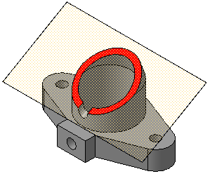
Figure 2.8 – Oblique section
Complex cuts are divided into:
- stepped , if the cutting planes are parallel (stepped horizontal, stepped frontal) (Figure 2.9);
- broken lines, if the cutting planes intersect (Figure 2.10).

Figure 2.9 - Complex - Stepped cut

Figure 2.10 – Complex – Broken cut
The cuts are called:
- longitudinal, if the cutting planes are directed along the length or height of the object (Figure 2.7, c);
- transverse, if the cutting planes are directed perpendicular to the length or height of the object (Figure 2.7, d).
Sections that serve to clarify the structure of an object only in certain, limited places are called local .


Figure 2.11 a - Examples of making cuts

Figure 2.11 b - Examples of making sections combined with views
2.2.2 Making cuts
Horizontal, frontal and profile sections can be located in place of the corresponding main views (Figure 2.11, a, b).
Part of the view and part of the corresponding section can be connected by separating them with a solid wavy line or a line with a break (Figure 2.11, b). It should not coincide with any other lines in the image.
If half of the view and half of the section are connected, each of which is a symmetrical figure, then the dividing line is the axis of symmetry (Figures 2.11, b; 2.12). You cannot connect half a view with half a section if any line of the image coincides with the axial line (for example, an edge). In this case, connect a larger part of the view with a smaller part of the section, or a larger part of the section with a smaller part of the view.
It is allowed to separate the section and the view by a thin dash-dotted line coinciding with the trace of the plane of symmetry not of the entire object, but only of its part, if it represents a body of rotation. When connecting half of the view with half of the corresponding section, the section is located to the right of the vertical axis and below the horizontal (Figure 2.12).

Figure 2.12

Figure 2.13
Local cuts are highlighted in the view as solid wavy lines. These lines should not coincide with any other lines in the image (Figure 2.13).
Sectional figures obtained by different cutting planes when performing complex cut, do not separate one from the other by any lines.
A complex stepped section is placed in place of the corresponding main view (Figure 2.9) or anywhere in the drawing.
With broken cuts, the secant planes are conventionally rotated until they align into one plane, and the direction of rotation may not coincide with the direction of view. If the combined planes turn out to be parallel to one of the main projection planes, then the broken section can be placed in the place of the corresponding type (Figure 2.10).
When rotating the cutting plane, the elements of the object located behind it are drawn as they are projected onto the corresponding plane with which the alignment is made. It is allowed to connect a stepped cut with a broken one in the form of one complex cut.
2.3 Sections
Section called the image of a figure obtained by mentally dissecting an object with a cutting plane(Figure 2.14).
The section shows only what falls directly into the cutting plane.
The cutting planes are chosen so as to obtain normal cross sections.
Sections are divided into:
- sections included in the section (Figure 2.15, a);
- sections not included in the section Figure 2.15.b).
Sections not included in the composition are divided into:
- issued(Figures 2.14, a; 2.14, c; 2.15, b; 2.16, a; 2.17, a; 2.18);
- superimposed(Figures 2.14, b; 2.16, b; 2.17, b).
Extended sections are preferable and they can be located in the gap between parts of the same type, on the continuation of the trace of the cutting plane with a symmetrical section figure, at any place in the drawing field, as well as with a rotation (Figures 2.14, a, c; 2.15, b; 2.16, a; 2.17, a; 2.18, a).
To depict the trace of the cutting plane in the drawing, use a thick open line with arrows indicating the direction of view, and designate the cutting plane in capital letters of the Russian alphabet. The section is accompanied by an inscription of type AA (Figure 2.14).
The ratio of the sizes of the arrows and the strokes of the open line must correspond to Figure 2.14. The starting and ending strokes should not intersect the outline of the image.
Letter designations are assigned in alphabetical order without repetition and, as a rule, without gaps. The font size of the letter designations should be approximately two times larger than the size of the digits of the size numbers. The letter designation is located parallel to the main inscription, regardless of the position of the cutting plane.
In the general case, when the section is located in any free space in the drawing, the position of the trace of the cutting plane is depicted as indicated above, and the image of the section is accompanied by an inscription corresponding to the name of the cutting plane (Figure 2.14, a; 2.15, b).
In the cases shown in Figures: 2.14, b, c; 2.17, a, b; 2.18, a (superimposed sections; sections made in a break in the view; sections made on the continuation of the trace of the cutting plane) - for symmetrical sections the trace of the cutting plane is not depicted and the section is not accompanied by an inscription.

Figure 2.14 A

Figure 2.14 b

Figure 2.14 V
For asymmetrical sections , located in a gap, or superimposed, the trace of the cutting plane is depicted, but not accompanied by letters (Figure 2.16). The section is also not accompanied by an inscription.
The outline of the extended section is drawn with a thick solid line (the main line), and the outline of the superimposed section is drawn with a thin solid line, while the outline of the view is not interrupted.
 |
|
| A | b |
Figure 2.15
 |
|
| A | b |
Figure 2.16

Figure 2.17 A,b
 |
|
| A | b |
Figure 2.18
For several identical sections of the same object, the section lines are designated by one letter and one section is drawn. If the cutting planes are directed at different angles, then the “Rotated” sign is not applied (Figure 2.19).

From GOST 3453-46 it follows that in order to identify the internal outlines and shapes of parts of the object depicted in the drawing, it is necessary to use sections, and where necessary, sections, depending on the images obtained on the projection planes.
1. If an object is designed in the form of a symmetrical figure (Fig. 155, a), it is recommended to make a simple section (Fig. 155, b): in the main view - vertical-longitudinal, in the top view - horizontal and in the left view - vertical-transverse . You can connect half the view with half the section (Fig. 155, c), the division between which should be the center line. In this case, hidden shapes are not shown in the connected view. This method of making the cut is preferred. When using a horizontal cutting plane, it is recommended to make half of the section either to the right of the vertical axis or downward from the horizontal, depending on which axis the halves of the view and section are symmetrical with respect to. If the image is symmetrical to both axes, then half of the cut is recommended to be made to the right of the vertical axis (Fig. 155, d).
2. If the object is designed in the form of an asymmetrical figure (Figs. 156 and 157), then a simple or complex cut is used. In fig. 156 shows a simple one, and FIG. 157-complex (stepped) cuts.
3. In symmetrical figures, a center line is used to delimit the halves of the view and the section. If this may lead to any ambiguity, as, for example, when an outer or inner edge (the lines of intersection of two faces) coincides with the main or local center line, parts of the view and section are delimited by a breakout line. If it coincides with an outer edge, it is recommended to draw the tear line to the right of the edge (Fig. 158, a), and if it coincides with an internal edge, it is to the left of it (Fig. 158, b).
4. In stepped sections, when the traces of the cutting planes coincide with the main and local axial lines, the transition from one cutting plane to another is carried out in a random place, no demarcation line is made between the cutting planes (Fig. 157).
 5. When making cuts, traces of cutting planes should be marked with letters of the Latin alphabet or Roman numerals (Fig. 157), except for simple cuts (Figs. 155 and 156), when the cutting plane passes through the main or local center line of the figure or when the configuration and location of the cut are easily determined by the direction of the cutting plane. Let's look at these cases with examples.
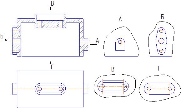
Example 1. Let us be given a cylinder with a transverse through hole of a triangular shape, the image of which is given in Fig. 159 a. Cuts need to be made.
For the main view we do not make a cut, since in this view the cylinder has no hidden shapes. In the views on the left and above there are invisible straight lines AB, CD and EF, the projections of which are designated according to these views: a""b", c"d", e"f" and ab, cd, ef. To reveal the lines of the invisible contour, we use cuts Since the cylinder was designed in both views in the form of a symmetrical figure, we use simple cuts to connect half of the view and half of the section (Fig. 159 b). For the view on the left, we make a vertical transverse cut, and for the top view, a horizontal one. In one of these views the section is marked with the letters KLM, in the other this mark is not made. This designation of sections is made in accordance with paragraph 5. Note also that, unlike the view on the left, in the top view the line of demarcation between the halves of the view and the section is the contour straight line AB. Such the distinction between the halves of the view and the section somewhat violates the instructions in paragraph 3. However, to identify the straight lines EF and AB, due to the lack of a local centerline, it is necessary to use a section according to KLM. In this regard, the demarcation line between the halves of the view and the section became a projection coinciding with the centerline straight AB. In this case, the direct CD is not drawn.


In the profile view, the connected view is shown without dashed lines. This convention is adopted to make the drawing easier to read. It is used whenever an object is designed in the form of a symmetrical figure, and the part of it that is symmetrical to the connected view is shown in section (see point 1).
Example 2. In fig. 160 is given a circular truncated cone intersected by a prism with a square base. In this example, it is easy to find the application of the conventions discussed above.
As in the previous example, the cone was projected in all projections in the form of a symmetrical figure. However, it is easy to notice that the main view and section in the left view are similar to those in FIG. 159 b. The only peculiarity of this example is that with the same KLM section for the top view, the demarcation line between the halves of the view and the section is the center line (see point 3).
The inscription - according to KLM is given only for a horizontal projection, since the horizontal plane separates the part of the figure limited by the KL plane (see point 5).
Example 3. In fig. 161, and given is a straight prism with a regular hexagonal base, pierced by two other prisms, one of which has a square base and an axis coinciding with the axis of the main prism. The second prism is triangular, with edges perpendicular to the vertical plane of projection.
Projections of the prism in Fig. 161, and are shown without cuts.
Internal contour lines are shown in all projections as dashed lines. You should pay attention to the vertical projection of the rib, which coincides with the axis of symmetry. In these cases, the edge is drawn as a contour line.


To reveal the internal outlines of this prism, we will make the necessary cuts (Fig. 161, b). The most convenient thing here is to use breaks, since the figure has edges on the outside and inside that coincide with the axis of symmetry. For the top view, it is advisable to use a KLM section, similar to the top view for Fig. 159b.
For independent exercise in Fig. 162 is given in three projections of a prism intersected by a pyramid and a prism. Required:
1) outline the necessary cuts for each projection;
2) draw with solid lines the internal outlines revealed by the cut;
3) shade the cuts;
4) mark the corresponding cuts with letters.
Using the examples discussed above, instructions are given on how to reveal the hidden outlines of the body using cuts.
The solution to the problem is no different from what was said if instead of a geometric body a technical detail is depicted. Let's look at a few examples.
Rack(Fig. 163). There are two cylindrical holes inside the rack: one for the roller and the second for lubrication. The flange has holes for mounting.

To identify them in the drawing, a vertical longitudinal section is given in the main view at the junction of the halves of the view and the section. No cut is required for the top view. The cut for the left view, except for the oil hole, cannot reveal any other hidden lines. In such cases, a breakthrough is made. In this case, the pullout is used to open the contour of the lubrication hole.
An incomplete projection relative to the horizontal axis of symmetry for the top view makes it possible, in order to save the number of graphic operations, to limit ourselves to half the image. This method is used when designing bodies that are symmetrical about their axes.

Valve body. The valve body is a more complex technical part than the rack discussed in the previous example. In fig. 164, and the valve body is shown without a cut, and in FIG. 164, b-section.
In order to correctly resolve the issue of the necessary cuts in the drawing of the valve body, we carefully examine it from the outside and inside. We make sure that the part is completely symmetrical relative to its axes.
The symmetrical shape makes it appropriate for all three projections to use combined sections: for the main view - vertical-longitudinal, for the left view - vertical-transverse and for the plan - horizontal.
It is easy to see that the vertical longitudinal section in Fig. 165 combines half of the view shown in FIG. 164, a, and half of the section shown in Fig. 164, b. This way of connecting the view and the section is allowed only for symmetrical parts.
If we consider Fig. 164, a and b separately, then each of these images has its own shortcomings. For example, the housing image in FIG. 164, but hides the internal outlines and therefore makes the drawing difficult to read, and the full sectional image in FIG. 164, b makes it impossible to have a judgment about the external shapes of the part of the body that fell off when cutting the drawing. The above disadvantages are eliminated if you combine half the view and half the section (Fig. 165). The cut lines are shown here as centerlines.

Globe valve body(Fig. 166, a and b). Unlike the valve body, the body of the straight-through valve does not have internal symmetry: the front partitions of the valve are directed in different directions (Fig. 166,a).

For a profile projection, a vertical transverse section can be used in combining the halves of the view and the section, since the body of the straight-through valve is projected onto the profile plane symmetrically to the vertical axis. As for the horizontal projection, there is no need to make an incision here. The presence of a saddle, frontal septa, and transitions from the saddle to the body can lead to misinterpretation of the section.

Feed valve body(Fig. 167, a, b and c). As already mentioned, it is customary to make complete sections of asymmetrical parts, therefore, in the main view of the drawing of the supply valve body (Fig. 167, c), a vertical longitudinal section is used.
A vertical transverse section was made on the profile projection. As for the horizontal projection, the symmetry of the part relative to the frontal axial plane allows it to be depicted in section only as shown in this projection.
For asymmetrical shapes, similar to the considered body of the supply valve, partial cuts (tearouts) are often used instead of cuts to reveal the internal outlines.
A cut is an image of an object mentally dissected by one or more planes. The section shows what is obtained in the secant plane and what is located behind it (Fig. 5.9). It is allowed to depict not everything that is located behind the cutting plane, if this is not required to understand the design of the object.
The cuts can be:
- horizontal - the cutting plane is horizontal (Fig. 5.11);
- vertical - the cutting plane is vertical. A vertical section is called frontal (see Figures 5.9 and 5.10) if the cutting plane is parallel to the frontal plane of projection, and profile if the cutting plane is parallel to the profile plane of projections (Figure 5.12);
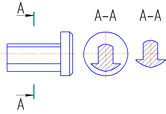
- inclined - the cutting plane is inclined to the horizontal plane of projections (Fig. 5.13, a). An oblique section may be depicted with a rotation. In this case, the same sign is added to its designation as for rotated views (Fig. 5.13,6).

Depending on the number of cutting planes, cuts are divided into simple - with one cutting plane, and complex - with two or more cutting planes.
 A complex cut is called stepped if the cutting planes are parallel (Fig. 5.14), and broken if the cutting planes intersect at an angle greater than 90° (Fig. 5.15). It is allowed to use complex cuts, similar to section A-A in Fig. 5.16, and broken lines - in Fig. 5.17 when the projection direction does not match the rotation direction.
 When rotating the secant plane, the elements of the object located behind it are drawn as they are projected onto the corresponding plane to which the alignment is made (keyway and prismatic protrusion in Fig. 5.18).
If necessary (Fig. 5.19), expanded cuts can be used. In this case, a sign according to Fig. is placed above the images. 5.8, c.
 A section that serves to clarify the structure of a part only in a separate limited place is called local (partial).
It is limited in the view by either a wavy line or a line with kinks (Fig. 5.20). The ends of the broken line should protrude beyond the image contour by 2..4 mm (Fig. 5.20). These lines must not coincide with any other lines in the image.


It is allowed to connect part of the view and part of the corresponding section, separating them with a broken line (Fig. 5.21) or a wavy line (Fig. 5.23). If half of the view and half of the section are connected, each of which is a symmetrical figure, then the dividing line is the axis of symmetry (Fig. 5.22 and Fig. 5.23, section A-A), except in cases where a contour line is projected onto the axis of symmetry (Fig. 5.23 ). In this case, as a rule, the incisions are located to the right of the vertical or downward of the horizontal axis of symmetry. It is allowed to separate the section and view by an axial line in cases similar to those shown in Fig. 5.24.
 In general, the cut designation contains an indication of the position of the cutting plane by the section line (with strokes of an open line), an indication of the direction of projection (arrows on the initial and final strokes) and a designation of the cutting plane and the cut with the same capital letter of the Cyrillic alphabet, starting with A, without gaps and repetitions (see Fig. 5.39). The starting and ending strokes should not cross the outline of the image. The letters are placed near the arrows (if necessary and in places of inflection) on the outside of the corner. The font size is 1.5...2 times larger than that accepted for dimensional numbers. The value of L is according to the situation, preferably at least 3 mm (Fig. 5.25).
 If necessary, the starting and ending strokes can be located inside the contour (Fig. 5.26).
 They do not indicate the position of the secant plane, the direction of projection, and do not apply letter designations if the secant plane coincides with the plane of symmetry of the object and is parallel to one of the main projection planes (vertical sections in Fig. 5.10 and 5.23 and horizontal in Fig. 5.11).
It is allowed to indicate the position of the cutting plane and the direction of projection without letter designations according to Fig. 5.27. Prerequisites for all these three cases are the execution of images according to method E and location in direct projection connection, ensuring an unambiguous understanding of the drawing.